The Flying Machines of the Magnificent America’s Cup Men
Published on December 11th, 2019
Dutch scientist Joop Slooff, who authored a book to detail his role in the design of the infamous winged keel of 1983 America’s Cup winner Australia II, provides early analysis of what to be looking at as the AC75s hit the water for the 2021 America’s Cup.
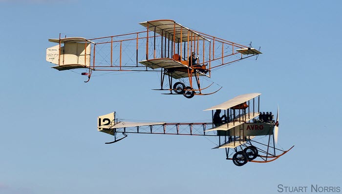
More than 50 years ago the British produced a fantastic movie: Those Magnificent Men in their Flying Machines. It plays in 1910, just after the dawn of aviation, with an incredible collection of flying machines of all sorts, all designed and built to win the Great Air Race from London to Paris.
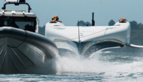
Exciting times again at this moment. We have, again, Magnificent Men with Flying Machines that all want to win a great race and the associated trophy: the America’s Cup. Again we see flying machines of different configurations, at, or just after the dawn of another new technology: foiling sailing yachts. And again the combatants are spying on each other, are (perhaps) making secret deals, or setting up other intrigues and are prepared to bend the rules (or worse) in order to win.
As we now have four of the new AC75 configurations having surfaced, there has been quite a lot of commentary, analysis, and speculation on the background of the substantial differences between the configurations.

Most of these have concentrated on the shape of the hull and its consequences for the transition from the displacement mode to the foiling mode and for the aerodynamic drag of the hull in foiling mode. Foil characteristics were discussed also to some extent.

One important aspect that I haven’t seen addressed so far is the balance between the aerodynamic lift of the hull and the hydrodynamic lift of the foils. In this context it is essential to realize that aerodynamic as well as hydrodynamic lift inevitably produce induced drag or drag-due-to-lift.
This induced drag is proportional to the square of the lift divided by the product of half the square of the velocity, the square of the span and the density of the fluid. In terms of a formula this can be written as ![]() .
.
For the aerodynamic lift L of the hull, which acts like a thick, low aspect ratio wing, the span ‘b’ is about the same as the maximum beam of the hull, say 4m. The maximum of the span of the foils is also 4m. For a true wind speed of 12kts the (apparent) wind speed V of the hull is about 27 % more than the speed of the foils in the water. Most importantly, there is a huge difference (about a factor 850) between the density ρ of air and that of water.
The figures just given imply that the drag due to aerodynamic lift of the hull is about a factor 500 larger than the drag due to hydrodynamic lift of the foils. This means that the aerodynamic lift of the hull should be kept as close to zero as possible and to let the foils do all the lifting work.
Another point that I haven’t seen addressed yet is the ‘height of the flight’. The efficiency of the rig requires that it should be as close as possible to the water surface, with zero heel. At the same time it is good for the efficiency of the foils if they are kept at some distance from the water surface.
This will, almost automatically, be the case if the ‘height of the flight’ is small. All this means that the control and stability system should keep the height of the flight as small as possible with, at the same time, zero aerodynamic lift on the hull and zero heel. An interesting challenge!
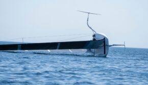
The foils we have seen so far are also significantly different. See below. This is understandable, at least partly, because the rules allow a certain amount of freedom and it is not immediately obvious how this can best be utilized.

As shown in the next figure, from the design rules, the projection of the foil in the vertical, cross-sectional plane must be within the shaded area indicated in the figure. Drawn into this figure are three typical possible choices for the cross-sectional extent of the foil.

Of the two plane foils the one with the small span (about 2.25m) is attached to a short strut with little wetted area. This implies small friction drag of the strut but a high level of induced drag because of the small span. The big one utilizes the maximum possible span but requires a longer strut with more wetted area (less drag-due-to-lift but more frictional resistance).
Anything in between these two extremes is also possible. The small option obviously means that the foil has to operate close to the water surface which easily induces negative effects like loss of lift, increased induced drag and ventilation/cavitation phenomena that also increase resistance. The large foil option will operate further away from the water surface and be less vulnerable for the phenomena just mentioned for the small foils.
The third option, with anhedral, combines a short strut with the maximum span, implying less wetted area of the strut as well as the maximum possible span. This, by itself, is favourable but there are also negative aspects. One is that the foil will have to produce more lift because not all of the lift is in the vertical direction. Another is that the strut-foil junction is close to the water surface, implying a greater risk for local loss of lift and ventilation/cavitation.
The design rules also imply that the longitudinal extent of the foils is limited to 2.0m and that they are symmetric with respect to a (vertical) plane through the strut. This means that the choice of foil planform is also limited. The figure below illustrates some of the possibilities. Foils with a small chord length and a small area can have some sweep-back (or sweep-forward). This is favourable for postponing cavitation at high boat speeds and the friction drag of the foils, but not for lift. Sweep also introduces other, e.g. structural, complexities.
The foils are allowed to have trailing-edge flaps to increase the lift at low boat speeds and promote an early transition from the displacement mode to the foiling mode. The flaps will be most effective when the trailing- edge has zero sweep. The foil area is also an important parameter for the transition or “take-off” speed.

Another point of interest is the flow at and around the intersection between the foils and the strut. This can be dealt with in different ways. E.g. by inserting a bulb at the intersection and/or by a longitudinal off-set between the foils and the strut. In all cases it is a prerequisite that there are properly shaped fillets at the leading edge of the intersecting foil with the bulb or the strut and the intersection of the strut with the bulb to avoid flow separation.
Considering the foils that have surfaced so far we can see that all seem to have chosen for the large span option. This is not surprising because it is easily calculable that the sum of induced drag of the foil and friction drag of the strut is smaller for the foil with the maximum allowable span. Besides there is the smaller risk of adverse effects due to the larger distance from the water surface.
We can also see that three of the four have a significant amount of anhedral and a bulb in the intersection between the strut and the foils. The bulbs probably contain some ballast. Not all of the configurations seem to satisfy all the requirements for hydrodynamically proper intersections.
 The most ‘sexy’ configuration is Luna Rossa’s, which sports a W-kind of an- + dihedral plus a couple of ‘gadgets’ at the leading edge. The gadgets look like vortilons. On aircraft they serve to improve the high lift performance with extended trailing-edge flaps.
Needless to say that the trade-off considerations for the foils are many and that some are fairly complicated. So don’t be surprised if the teams will be experimenting for quite some time to come.
The Magnificent Men still have a lot of work to do before the Great Race can start!
Joop Slooff has also written The Science behind Sailing to provide the New Testament of the aero- and hydromechanics of sailing. Contains full and scientifically justified descriptions of the dependence of the performance of sailing yachts on their configuration and trim and the underlying physical mechanisms.
In addition to Challenges from Italy, USA, and Great Britain that were accepted during the initial entry period (January 1 to June 30, 2018), eight additional Notices of Challenge were received by the late entry deadline on November 30, 2018. Of those eight submittals, entries from Malta, USA, and the Netherlands were also accepted. Here’s the list:
Defender:
• Emirates Team New Zealand (NZL)
Challengers:
• Luna Rossa (ITA) – Challenger of Record
• American Magic (USA)
• INEOS Team UK (GBR)
• Malta Altus Challenge (MLT) – WITHDRAW
• Stars + Stripes Team USA (USA)
• DutchSail (NED) – WITHDRAW
Of the three late entries, only Stars+Stripes USA remains committed, but they still must complete the entry fee payment process before they will be eligible to race. They have already paid their initial payment but as a late entry challenger under the Protocol they also have a liability to pay a US$1million late entry fee due in installments by October 1, 2019. This deadline coincided with the venue schedule which has the construction of their team base beginning in late 2019, which we assume was done in the event the team is unable to fulfill their payment deadline. However, it is not yet confirmed if they have paid the fee.
Key America’s Cup dates:
✔ September 28, 2017: 36th America’s Cup Protocol released
✔ November 30, 2017: AC75 Class concepts released to key stakeholders
✔ January 1, 2018: Entries for Challengers open
✔ March 31, 2018: AC75 Class Rule published
✔ June 30, 2018: Entries for Challengers close
✔ August 31, 2018: Location of the America’s Cup Match and The PRADA Cup confirmed
✔ August 31, 2018: Specific race course area confirmed
✔ November 30, 2018: Late entries deadline
✔ March 31, 2019: Boat 1 can be launched (DELAYED)
✔ 2nd half of 2019: 2 x America’s Cup World Series events (CANCELLED)
October 1, 2019: US$1million late entry fee deadline (NOT KNOWN)
February 1, 2020: Boat 2 can be launched
April 23-26, 2020: First America’s Cup World Series event in Cagliari, Sardinia.
During 2020: 3 x America’s Cup World Series events
December 10-20, 2020: America’s Cup Christmas Race
January and February 2021: The PRADA Cup Challenger Selection Series
March 2021: The America’s Cup Match
AC75 launch dates:
September 6 – Emirates Team New Zealand (NZL), Boat 1
September 10 – American Magic (USA), Boat 1; actual launch date earlier but not released
October 2 – Luna Rossa (ITA), Boat 1
October 4 – INEOS Team UK (GBR), Boat 1
Details: www.americascup.com

Related Posts

New era for America’s Cup →
38th America’s Cup: One year out →
Capsize for French AC team →