
Foiling boats and flying boats
Published on March 10th, 2021
It was not the intent of the AC72 Rule to promote a foiling multihull for the 34th America’s Cup in 2013, but that’s what happened, and ever since the sport has been seeking how to benefit from this progression.
As we witness the AC75s in 36th edition, Joop Slooff, author of The Science behind Sailing and Australia II and the America’s Cup; the untold, inside story of The Keel, compares these flying monohulls with a distant cousin:
It is, perhaps, interesting to realize that there are certain similarities in the physics involved with foiling sailing boats and the physics involved with flying boats (aka float planes or seaplanes). The most important being that both have to go through a transition from the displacement mode to the flying mode and have to attain a certain minimum speed to become foilborn or airborn.
In the case of the foiling sailing boat, the foils, or water wings, gradually take over the vertical lift from the buoyancy of the semi-submerged hull. The foils replace that by the hydrodynamic lift that they begin to generate when the boat starts to move and the boat speed increases.

In the case of the flying boat the buoyancy of the hull is gradually replaced by aerodynamic lift of the wings in the air. This aerodynamic lift increases when the apparent wind speed, as felt by the wings, increases. This process is most effective when the flying boat starts directly into the direction of the true wind. Then, all increase of the “boat speed” is turned into an increase of the apparent wind speed felt by the wings.
In both cases, the hydrodynamics of the flow about the semi-submerged hull are the cause of an adverse effect with respect to the lift: with increasing boat speed the flow creates increasing suction at the bottom of the hull which results into negative hydrodynamic lift. This increases with boat speed (see the figure below).
Needless to say, this requires more lift of the hydrofoils or aerowings and, hence, more speed in order to get foilborn or airborn. Moreover, the latter is more difficult due to additional drag-due-to-lift felt by the foils or wings.

Vertical hydrodynamic force (negative lift) caused by locally high flow velocity at the bottom of a hull.
In the case of the flying boat, the shape of the bottom of the hull is such, with a backward facing step, that it prevents too much negative lift. The step causes the flow to break away at its corner and and acts like a “lift dumper” or spoiler on an aircraft wing. Without it, it is almost impossible for a flying boat to take off.


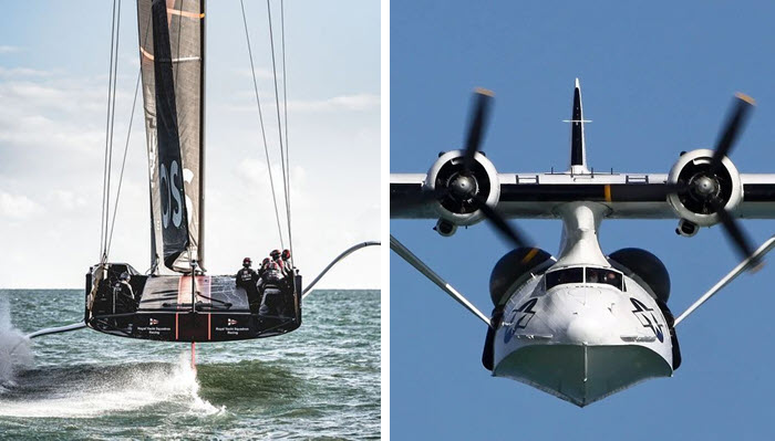
Britannia ll
At this point it is interesting to note that only one of the AC36 contenders has steps at the bottom of the hull that might serve a similar purpose as the step at the bottom of a flying boat: Britannia II of INEOS Team UK.
It is not the central, longitudinal, thick ridge I am referring to (that has a different function, to be addressed later), but the somewhat “pancake-like shape” on the rear half of the bottom of the hull. It may well be that a step with this sort of shape is better suited for its purpose when the hull is subject to leeway. The latter is the case with the sailing boat, which has to negotiate the side force produced by the sails. However, a flying boat in displacement mode has zero leeway.
An adverse effect of the kind of steps just discussed is more parasitic drag in the flying mode.
There are, of course, more differences between foiling sailing boats and flying boats. In both cases trailing-edge flap deflection and angle-of-attack (pitch) control is used to allow the foils or wing to generate sufficient lift.
 In the case of the flying boat, this is realized by deflecting control surfaces on the horizontal tailplane (stabilizer). The angle of attack also allows the V-shaped front part of the hull to generate some lift by planing. The rear part of the hull is cut away to allow a higher angle of attack without hitting the water surface when rotating to the higher angle of attack.
In the case of the sailing boat, the lift on the foils is also controlled by trailing-edge flap deflection and angle of attack (pitch) control. In this case the pitch control is realized by raking the rudder, with its horizontal foil at the tip, backward and forward.
There is also a certain amount of similarity between the behavior, as a function of speed, of the forces acting on a foiling sailing yacht and those acting on a flying boat. The figures below given a qualitative comparison. Both figures present a picture of the variation of lift and drag as a function of the speed of the vehicle.
In the top figure, for the flying boat, we see the hydromechanic lift decrease and the aerodynamic lift increase with speed, until lift-off when the hull no longer touches the water and all of the weight is carried by the wing. The lower half of the figure presents the variation of drag as a function of speed.
Note that, in the displacement mode, the hydrodynamic drag increases rapidly with speed until it reaches some kind of a plateau, called “the hump”. At this point the hydrodynamic drag begins to level off or even decreases due to the fact that the submerged volume of the hull is now much smaller than at zero speed, leading to less hydrodynamic friction drag and less wave-making resistance. At the same time the aerodynamic drag keeps increasing with speed.


Note that the figure also gives the variation with speed of the thrust from the propellers mounted on the wing. It will be clear that the vehicle will only be able to accelerate as long as the thrust is bigger than the total drag which is the sum of the hydrodynamic and the aerodynamic drag. Steady flight occurs when the aero drag line intersects the thrust line.
In the corresponding figure for the foiling sailing boat, we can see the hydrostatic lift due to the buoyancy of the submerged part of the hull decreases progressively with boat speed, with a corresponding increase of the vertical hydrodynamic lift of the foils.
Note that there is no aerodynamic lift because the sails cannot produce any vertical force component due to their vertical orientation and the vertical aerodynamic force on the hull is kept as small as possible. The reason for the latter is that aerodynamic lift on a slender body like a sailing yacht hull generates a very large amount of drag-due-to-lift (as discussed in an earlier article.
The drag figure for the foiler also exhibits a kind of “hump” in the hydrodynamic drag, basically for the same reasons as in the case of the flying boat. A difference with the flying boat is that the hydrodynamic drag does not disappear at lift-off. The reason is that the foils and struts always generate friction drag, drag-due-lift, and a small amount of wave-making resistance plus additional drag due to other hydrodynamic phenomena like cavitation, ventilation, and spray.
As in the case of the flying boat, the thrust, now the driving force produced by the sails, must be larger than the sum of the hydro and aero drag in order to accelerate.
The driving force for a given set and trim of the sails depends primarily on the apparent wind angle and the windspeed. This is shown by the next figure, which gives an impression of the driving force as a function of the apparent wind angle for different levels of the ratio Vb/Vt (boat speed divided by true wind speed).
The driving force is seen to attain its maximum at an apparent wind angle of about 90 degrees at very low boat speeds, decreasing to about 50 degrees at Vb/Vt ≈ 0.5. The latter corresponds roughly with the lift-off speed for moderate wind speeds.

(Editor’s note: The above graph has been corrected after an error was found in the previous version.)
The implication of all this is that a foiler should first adopt a reaching course in order to get on its foils as soon as possible. When fully foiling, the apparent wind angle can be reduced further to about 15 degrees when sailing upwind and to about 25 degrees when sailing downwind for the best velocity-made-good.
What the figure also shows is that, at high boat speeds, the margin for attaining a driving force close to the maximum is a very narrow one. The helmsman must be very concentrated to stay at the best apparent wind angle.
The level of the driving force increases quadratically with wind speed. I.e., at a 6kts wind speed, it is only a quarter of that at 12kts. In other words, getting over “the hump” becomes increasingly difficult at low wind speeds.
The trimming of the sails is, of course, also important for the driving force. Low boat speeds (transition) require more camber and larger sheeting angles than high speed, upwind sailing.
Back to the central “ridge” at the bottom of the hull of the current AC75 America’s Cup contenders. Although they vary in precise shape, the defender and all challengers have adopted a long, central ridge or skeg at the bottom of the hull of their second boat.
To this author’s knowledge, their function is many-fold: The main purpose is probably to improve the efficiency of the sails by closing the gap between the bottom of the hull and the water surface. The mechanism is illustrated by the last figure.

When a yacht sails with a small to moderate apparent wind angle there is cross-flow over the top of the hull, and, in the case of the foiler, also around the bottom. When the gap between the bottom of the hull and the water surface is closed there is more cross-flow over the top of the hull. This is experienced by the lower part of the sail as a larger apparent wind angle, with a larger driving force as a result.
The central ridges probably also reduce the suction at the bottom of the hull in the displacement mode with leeway. Other functions are reduction of the impact of slamming when the boat falls off its foils or hits a wave and improvement of the directional stability in the foiling mode.

Related Posts

Taking first steps toward America’s Cup →

Using virtual reality for sailing education →

Mighty Mary and 1995 America’s Cup →